White Dwarf Combustion Chamber
Overview
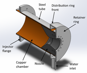
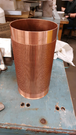
The White Dwarf combustion chamber uses a water-cooled jacket, with a graphite nozzle. The cooling channels are cut into an off-the-shelf copper tube using a CNC machine. The outer walls of the cooling jacket are made of stainless steel and are welded together.
Resources
Engineering Drawings
Copper Chamber
Made of copper due to it's high thermal conductivity, which significantly reduces the thermal stress across the walls as well as the wall temperatures. If steel was used, the thermal stresses would be much higher (and would outweigh the gain received from steel's higher yield stress).
Temperature and pressure drop predictions were generated using Bamboo, and the results are available on the simulations GitHub page.
Nozzle
The nozzle is made of graphite, and is intended to be manufactured by Tokai Carbon Europe. It contains 16 holes that will contain M5 x '3D' helicoil inserts, allowing the nozzle to be pulled into the retaining ring, whilst simultaneously compressing the graphite gasket in between the nozzle and retainer ring. Graphite thread failure calculations are available on the simulations GitHub page.
Retainer Ring
The retainer ring is manufactured from a single large piece of stainless steel billet. It has an inlet for the water coolant, and is intended to be brazed to the copper jacket, and welded to the rest of the steel components.
Distribution Ring Front
The flat ring that encloses the inlet distribution ring is intended to be a water-jet cut piece of stainless steel. It will be welded to the steel tube and the retainer ring.
Steel Tube
The steel tube that encloses the copper fins will slide over the copper, and is not connected to the copper directly. It is intended to be a custom-made welded stainless steel tube, manufactured in the Dyson centre.
Water Pump
The engine uses an electric water pump to feed the cooling jacket, on a closed loop system. The water that leaves the cooling jacket returns to a main reservoir, where it is recycled so that the cooling jacket can operate indefinitely.
Injector Connection
Not yet designed. The injector-end flange is designed to connect to both the injector and the test stand.
Notes
- The outlet distribution ring needs to have a larger flow cross section, as right now it is very narrow, which causes very large pressure drops as the coolant tries to leave it. This would also cause uneven velocity distributions in the coolant channel, as the pressure would vary significantly around the outlet distribution ring.

